Partners
Client:
Digikey
Location:
Minnesota, USA
Task:
Electronic Dist.
Get a Free Quote
MaM Sense
Bioelectric signals are the total electrical current produced by the electrical current on the tissue, organ or cell. Although biopotentials differ according to the tissues and organs from which they originate, they generally have common signal characteristics such as low amplitude (10 μV-10 mV) and low frequency (0 200 Hz). Specialized electrodes and electronic systems are used to obtain these signals for clinical purposes. The system used in this field is usually named with the name of the target organ (such as Electrocardiography, Electroencephalography). Electrodes, amplifiers, signal adaptors, and signal display devices are used in order to measure these potentials, which are of very small amplitude. Surface electrodes that are attached to the skin are commonly used as electrodes (EOG, EMG, ECG) because they do not damage the tissues. Sometimes it is necessary to use a needle electrode to make more local measurements. Because the measured signals are very small, recording problems are encountered at every stage. Problems such as skin conductivity, body movement, electrode noise, interference from the mains, electromagnetic wave interactions further deteriorate the quality of the already small signal.
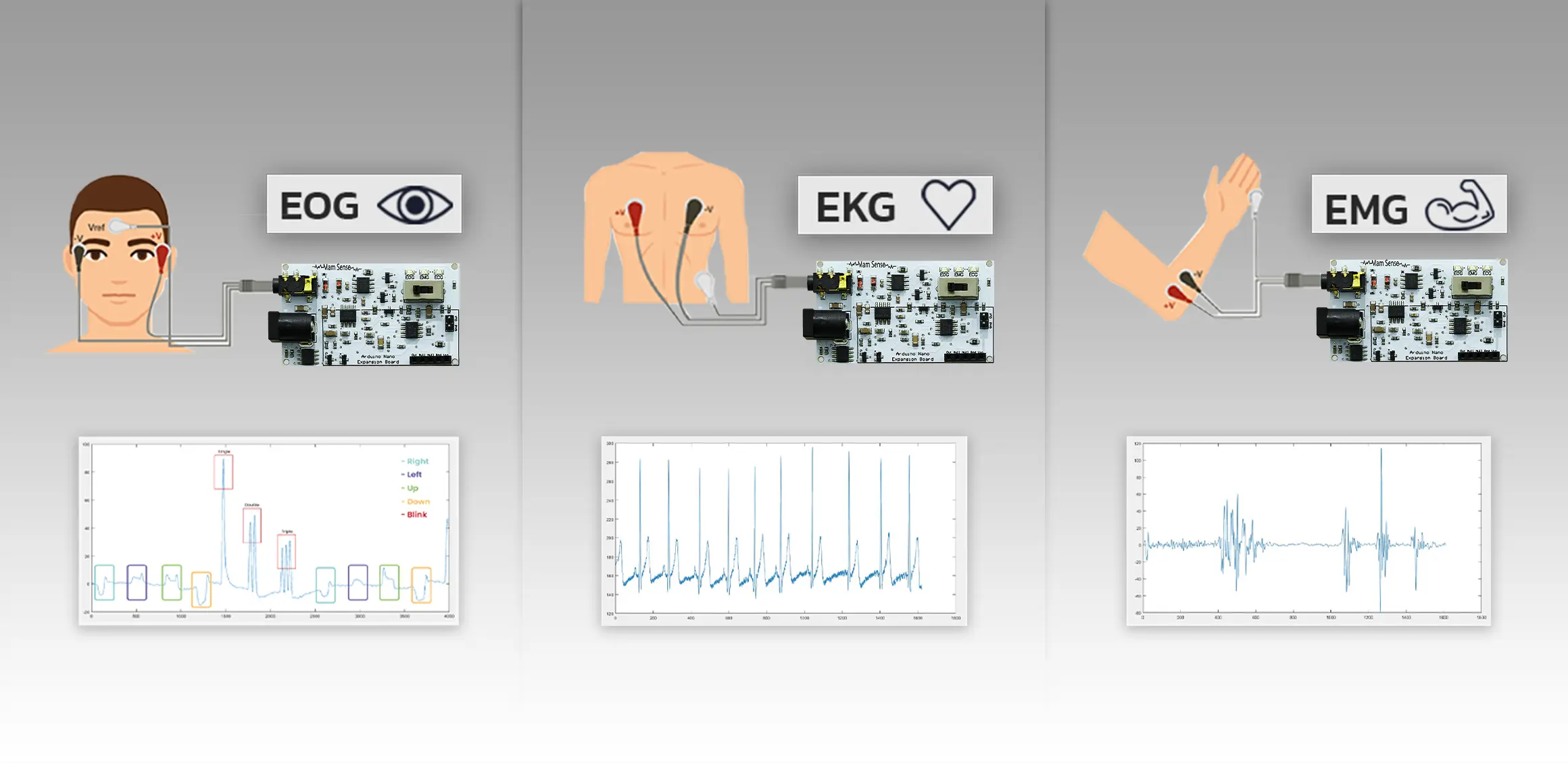
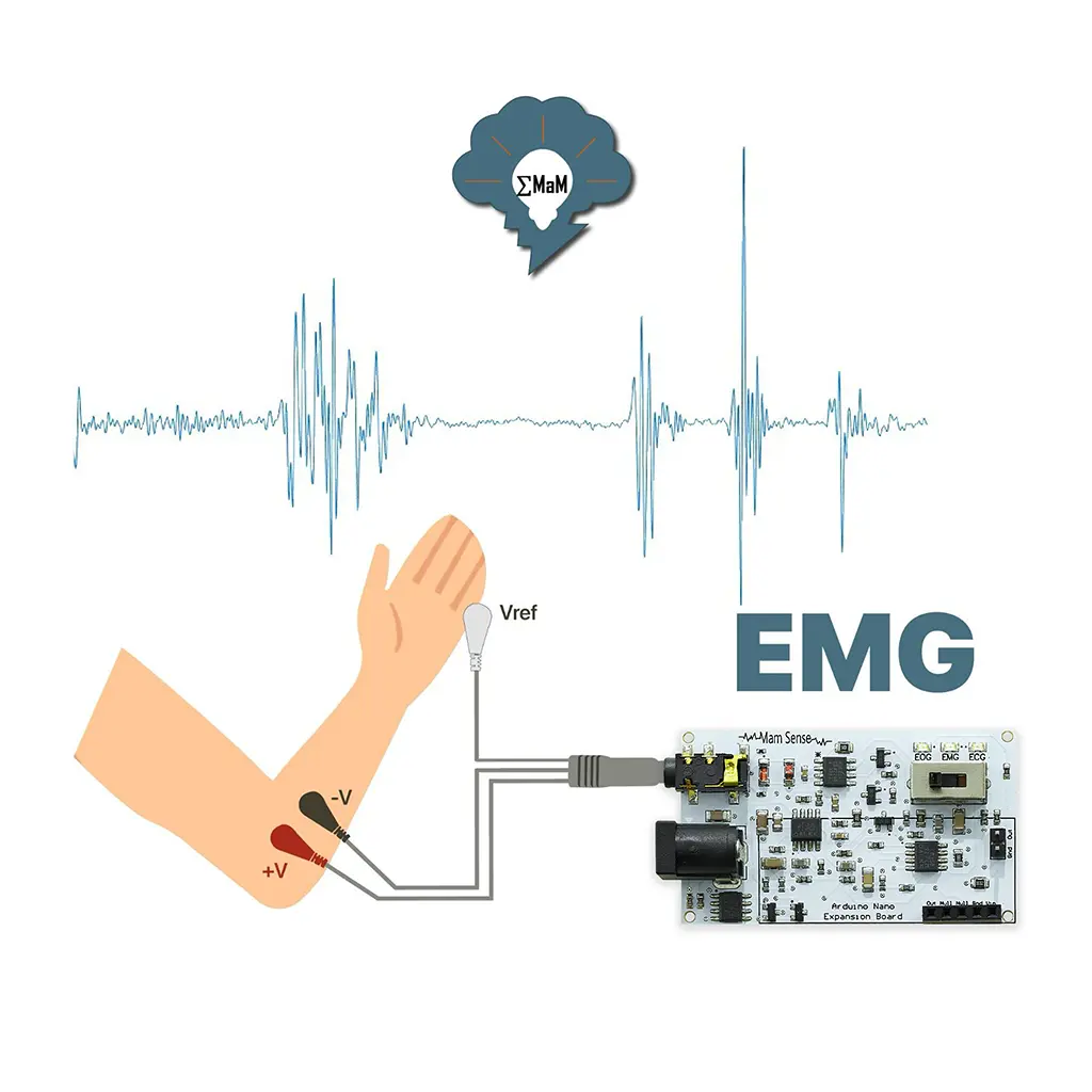
Although it is possible to measure the biopotentials in every tissue in principle, ECG, EMG and EOG recordings are most frequently performed for diagnostic purposes today. EOG is a method of recording the electrical potential between the cornea and the retina with the help of electrodes placed around the eye. EOG signal amplitude is 0.05-3.5mV and frequency is 1-10 Hz. Electromyography (EMG) is a technique for evaluating and recording the electrical activity produced by skeletal muscles. EMG signal amplitude is 1-10 mV and frequency is 0-500 Hz. Electrocardiography (ECG) is a method for measuring the electrical activity going through the heart by using external (skin)electrodes. ECG signal amplitude is 0.5-1 mV and frequency is 0.1-40 Hz. The aforementioned bioelectric signals are first amplified by using a differential amplifying circuit to have a gain of 101, then filtering is done using a high-pass filter in accordance with the frequency band of the signal. In this filtering stage, the cut-off frequencies of the bioelectric signals were adjusted to be 0.1 Hz, 20 Hz and 0.3 Hz for EOG and EMG and ECG, respectively.


All in One Biomedical Sensor
Cut-off Frequency for High-Pass Filter: 𝑓𝑐 = 1/2πRC Then, using the 2nd order Sallen-Key low-pass filter, the cut-off frequencies were adjusted to be 6 Hz, 500 Hz, 40 Hz and gain 3 for EOG, EMG, ECG, respectively. Gain: 𝐺𝑎𝑖𝑛 (𝐴𝑣) = 1 + Ra/Rb Cutoff Frequency If Resistor and Capacitor Values Are Different: 𝑓𝑐 = 1/2π√R1R2C1C2 Cutoff Frequency If Resistor and Capacitor Values Are Same: 𝑓𝑐 = 1/2πRC Cut-off Frequency for Low-Pass Filter: 𝑓𝑐 = 1/2πRC
Through a unique combination of engineering, design disciplines and expertise, MaM High Tech delivers world class solutions. We embrace holistic development and support for employees.
ARDUINO CODES
// For more info visit: https://mamhightech.com/MamSense.html

int fs=100;     // Sampling rate (Hz) Don't change!
float Ts = (float)1000/fs;   //Sampling Period (ms)

unsigned long counter = 0;
short data_buff[200];

//Templates for the eye movements.
short look_left[60] = {-6,-3,4,16,32,55,80,107,131,153,171,180,187,184,181,172,164,155,148,141,136,132,130,126,124,122,120,118,114,111,107,104,101,98,95,91,89,87,84,81,78,76,74,72,70,68,66,63,62,60,58,58,55,53,52,52,50,49,47,46};
short look_right[60] = {7,4,-3,-14,-29,-49,-69,-93,-115,-132,-144,-154,-156,-158,-156,-152,-146,-141,-137,-133,-129,-126,-123,-120,-117,-113,-110,-105,-103,-101,-98,-94,-93,-90,-88,-86,-84,-80,-79,-77,-75,-72,-71,-67,-66,-64,-62,-60,-57,-56,-54,-52,-51,-50,-49,-47,-46,-45,-43};
short left_right[60] = {2,5,10,18,30,46,62,78,90,102,107,113,110,109,104,97,92,86,84,78,75,71,67,62,58,50,41,30,15,-1,-15,-29,-37,-45,-48,-49,-48,-47,-43,-41,-37,-36,-34,-34,-30,-33,-30,-31,-29,-29,-28,-28,-26,-27,-26,-25,-24,-23,-23,-23};
short right_left[60] = {3,-2,-9,-19,-32,-49,-61,-77,-89,-99,-105,-108,-108,-107,-103,-98,-94,-90,-85,-81,-76,-69,-61,-49,-34,-19,-4,11,24,34,40,45,46,47,46,45,44,43,42,43,41,42,39,38,36,36,35,34,33,32,32,31,30,28,28,28,26,26,24,24};
short blink_left[60] = {-12,-6,16,32,53,69,79,82,79,66,52,38,23,13,5,1,-2,-3,-2,-3,-3,-3,-3,-2,-2,-2,-2,-2,-2,-2,-5,-6,-5,-4,-4,-4,-4,-3,-4,-4,-4,-3,-4,-4,-4,-4,-4,-4,-3,0,0,0,0,0,0,0,0,0};
short blink_right[60] = {6,2,-3,-13,-25,-40,-52,-65,-71,-74,-71,-65,-56,-44,-34,-26,-17,-12,-7,-4,-3,-2,-2,-2,-1,-1,1,1,0,0,0,0,0,0,0,0,0,0,0,0,0,0,0,0,0,0,1,1,1,2,1,1,0,0,0,0,0,0,0,0};

float pos_pk_thrs=50;               // If your horizontal eye movements are not detected
float pos_pk = pos_pk_thrs;         // lower these thresholds.
float neg_pk_thrs=-50;              //
float neg_pk = neg_pk_thrs;
int pos_pk_n=0;             // Designate the indices where peaks are detected
int neg_pk_n=0;             //

float left_blink_thrs = 200;        //  If horizontal movements are detected as blink increase
float right_blink_thrs = -200;      //  these thresholds.

boolean pos_pk_reached;
boolean neg_pk_reached;

float error=0;
float blink_err=0;
float quick_mov_err=0;
float err_left_thrs=6;         // If your horizontal eye movements are not detected increase the error thresholds.
float err_right_thrs=6;        // If other movements are detected as horizontal movements decrease the error thresholds.
float err_coef=2;              // If fast eye movements are detected as blink increase the coefficient(Must be in range 1-3).
  void setup() {
    Serial.begin(9600);
  }

  void loop(){

      delay(Ts);
      data_buff[counter%200] = analogRead(A2)-290;
    // Serial.println(data_buff[counter%200]);

// This block of code checks if the peak threshold is reached and records the value and its index
     if(data_buff[counter%200]>pos_pk){
        pos_pk_reached=true;
        pos_pk_n = counter%200;
        pos_pk = data_buff[counter%200];
      }

// Similarly this code checks if the negative peak threshold is reached and records the value and its index
      if(data_buff[counter%200]<neg_pk){ neg_pk_reached="true;" neg_pk_n="counter%200;" neg_pk="data_buff[counter%200];" }="" if="" positive="" peak="" is="" reached="" wait="" for="" 60="" more="" samples="" then="" start="" applying="" least="" mean="" square="" method.="" if(counter%200="=(60+pos_pk_n)%200" &&="" pos_pk_reached="" ){="" error="0;" blink_err="0;" quick_mov_err="0;" if((pos_pk="" -="" data_buff[(pos_pk_n+185)%200])="">= left_blink_thrs){  // Since blink signals are stronger than other movements if the blink threshold is reached
        Serial.println("Left Blink");                                    // there's no need to compare the signal with the templates.
        //Related drone command here...
       }

       else if((pos_pk - data_buff[(pos_pk_n+188)%200]) >= pos_pk_thrs){

          for(int i=0;i<60;i++){
            error += sq(look_left[i] - data_buff[(i+pos_pk_n+188)%200]*187/pos_pk);       // Compute the similarity between recorded signal and 'look left' movement.
          }

          for(int i=7;i<60;i++){
           blink_err += sq(blink_left[i] - data_buff[(i+pos_pk_n+193)%200]*82/pos_pk);    // Compute the similarity between recorded signal and 'blink' movement.
          }

          for(int i=11;i<60;i++){
            quick_mov_err += sq(left_right[i] - (data_buff[(i+pos_pk_n+189)%200])*113/pos_pk); // Compute the similarity between recorded signal and 'quick left' movement.
          }

          blink_err = sqrt(blink_err)/53;             // Normalize the error rates.
          error = sqrt(error)/60;                     //
          quick_mov_err = sqrt(quick_mov_err)/49;

          if(blink_err < error && blink_err*err_coef<quick_mov_err && blink_err<err_left_thrs){    // Compare the error rates and send the corresponding command.
            Serial.println("Left Blink");                                                          // Blink error is multiplied by error coefficient for error protection.
            //Related drone command here...
          } else if(error<blink_err && error<quick_mov_err && error<err_left_thrs){
            Serial.println("Looked Left");
            //Related drone command here...
          } else if(quick_mov_err<error && quick_mov_err<blink_err*err_coef*0.75 && quick_mov_err<err_left_thrs){
            Serial.println("Left then middle");
            //Related drone command here...
          }

       }
      neg_pk=neg_pk_thrs;
      neg_pk_reached=false;
      pos_pk=pos_pk_thrs;
      }

      // This part of the code is very similar to the left eye movements only for the right eye.
      if(counter%200==(60+neg_pk_n)%200 && neg_pk_reached){
        blink_err=0;
        neg_pk_reached = false;
        error=0;
        quick_mov_err=0;
        if( (neg_pk - data_buff[(neg_pk_n+185)%200]) <= right_blink_thrs){
          Serial.println("Right Blink");
          //Related drone command here...
        }

        else if( (neg_pk - data_buff[(neg_pk_n+188)%200]) <= neg_pk_thrs){

          for(int i=0;i<60;i++){
            error += sq(look_right[i] + data_buff[(i+neg_pk_n+187)%200]*158/neg_pk);
          }
          for(int i=8;i<60;i++){
            blink_err += sq(blink_right[i] + data_buff[(i+neg_pk_n+190)%200]*75/neg_pk);
          }
          for(int i=12;i<60;i++){
            quick_mov_err += sq(right_left[i] + (data_buff[(i+neg_pk_n+188)%200])*108/neg_pk);
          }

           error = sqrt(error)/60;
           blink_err = sqrt(blink_err)/60;
           quick_mov_err = sqrt(quick_mov_err)/60;


           if(blink_err < error && blink_err*err_coef<quick_mov_err && blink_err<err_right_thrs){
             Serial.println("Right Blink");
             //Related drone command here...
           } else if(error<blink_err && error<quick_mov_err && error<err_right_thrs){
             Serial.println("Looked Right");
             //Related drone command here...
           } else if (quick_mov_err<error && quick_mov_err<blink_err*err_coef*0.75 && quick_mov_err<err_right_thrs){
             Serial.println("Right then middle");
             //Related drone command here...
           }
        }
        pos_pk=pos_pk_thrs;
        neg_pk=neg_pk_thrs;
        pos_pk_reached=false;
      }
    counter++;
  }


</neg_pk){> // This Arduino code is written for MaM Sense Board EMG output. For more info visit: https://mamhightech.com/MamSense.html
// The program detects hand movements and sends commands to actuators. It creates notch filter to suppress AC power line noise at 50 Hz
//(60 Hz if you are located in North and South America.)
// For the full table: https://en.wikipedia.org/wiki/Mains_electricity_by_country.
// If single frequency filter is not sufficient for you, activate the related codes to filter 2nd or 3rd harmonics.
const short Fs = 1000; // Sampling frequency(Hz). Must be in range 500-1200 Hz. Default value: 1 kHz
const int Ts = 1e6/Fs; // Sampling period (us);
const short f0 = 50; // Cut-off frequency of the notch filter(Hz).
const short f1 = 150; // Second cut-off frequency(Hz). (Must be integer multiple of f0)
const float w0 = 2*3.1416*f0/Fs; // Digital cut-off frequency (rad/sample)
const float w1 = 2*3.1416*f1/Fs; //
const float p = 0.95; //Quailty factor. Must be between 0.8 and 0.995. Default value: 0.95
const float mag = (1 -2*cos(w0) +1)/(1 -2*p*cos(w0) + p*p); // Find magnitude of the filter at w=0 to set the DC gain to 1;
//Create the coefficient matrices for notch filter at f0
const float num[3] = {1/mag, -2*cos(w0)/mag, 1/mag};
const float den[3] = {1, -2*p*cos(w0), p*p};
//Optional dual frequency notch filter. Comment this code block out to use dual frequency notch filter
// Create the coefficient matrices for notch filter at f1
const float mag2 = (1 -2*cos(w1) +1)/(1 -2*p*cos(w1) + p*p);
const float num2[3] = {1/mag2, -2*cos(w1)/mag2, 1/mag2};
const float den2[3] = {1, -2*p*cos(w1), p*p};
//Convolve two filters to obtain dual notch filter at frequencies f0 and f1
const float num3[5] = {num[0]*num2[0], num2[0]*num[1]+num2[1]*num[0], num2[0]*num[2] + num2[1]*num[1] + num2[2]*num[0], num2[1]*num[2]+num2[2]*num[1], num2[2]*num[2]};
const float den3[5] = {1, den2[0]*den[1]+den2[1]*den[0], den2[0]*den[2] + den2[1]*den[1] + den2[2]*den[0], den2[1]*den[2]+den2[2]*den[1], den2[2]*den[2]};
unsigned long start_time=0;
unsigned long current_time=0;
short raw[100] = {0};
short emg[100] = {0};
unsigned long count=4;
float curr_avg,prev_avg; // Variables to store current and previous average
const float alpha = 0.1; // Moving average coefficient. If hand movements are not detected change this number.
const float prev_alpha = 1 - alpha;
const int avg_thrsh = 35; //If noise is detected as hand movements increase this threshold. If hand movements are not detected decrease it.
const int digPin = 13;
short command_counter=0;
void setup() {
Serial.begin(2000000);
start_time = micros();
pinMode(digPin, OUTPUT);
}
void loop() {
current_time = micros();
if(current_time - start_time>= Ts){
start_time = current_time;
raw[count%100] = analogRead(A2)-295;
//Filters only the 1st harmonic of the powerline noise
//emg[count%100] = round(raw[count%100]*num[0] + raw[(count-1)%100]*num[1] + raw[(count-2)%100]*num[2] - emg[(count-1)%100]*den[1] - emg[(count-2)%100]*den[2]);
//Comment the line below out if you experience high power line noise and need to use dual frequency notch filter. Filters 1st and 2nd harmonics.
emg[count%100] = round(raw[count%100]*num3[0] + raw[(count-1)%100]*num3[1] + raw[(count-2)%100]*num3[2] + raw[(count-3)%100]*num3[3] + raw[(count-4)%100]*num3[4] - emg[(count-1)%100]*den3[1] - emg[(count-2)%100]*den3[2] - emg[(count-3)%100]*den3[3] - emg[(count-4)%100]*den3[4] );
curr_avg = abs(emg[count%100])*alpha + prev_avg*prev_alpha; //Calculate the current average.
prev_avg=curr_avg; //
Serial.println(emg[count%100]);
if(command_counter>0){
command_counter--;
if(command_counter==0){ //Turn off the digital output if the muscle has been deactive for sufficient amount of time.
digitalWrite(digPin, LOW);
}
}
if(abs(emg[count%100]) - prev_avg >=avg_thrsh){ // Check if muscle movement is detected.
//Serial.println("");
if(command_counter==0){
digitalWrite(digPin, HIGH); //Turn on the motor or other actuators.
}
command_counter = Fs/4;
}
count++;
}
}
         // This Arduino/ESP32 code is written for MaM Sense Board ECG output. For more info visit: https://mamhightech.com/MamSense.html
// The program measures the heart rate and sends it to serial communication.

const short Fs = 250;    // Sampling frequency(Hz)
const int   Ts = 1e6/Fs;  // Sampling period (us)

//ADC configuration
const byte adc_in = A2; // ADC input pin.(For example A2 for Arduino Uno, 27 for ESP32)
const byte adc_bits = 10; // The resolution of your MCU's ADC
const byte default_bits = 10; // Don't change!
const float vref = 5; // Reference voltage of your MCU's ADC (V)
const float default_vref = 5 ;// Default reference voltage of the Arduino Uno (V) Don't Change
const float adc_scale = pow(2,default_bits-adc_bits)*vref/default_vref; // Scales the input signal
const float ecg_offset = 1.75; // DC offset of the Mam Sense Board ECG output. (V)
const float sig_offset = round(pow(2,default_bits)*ecg_offset/default_vref);

//Create the coefficient matrices for low pass filter at 35 Hz.
const float nm[7] = {0.00086, 0.00515, 0.01286,  0.01715,  0.01286,  0.00515, 0.00086};
const float dn[7] = {1,-3.09854,4.41644,-3.55659,1.68514,-0.44112,0.04956};

unsigned long start_time=0;
unsigned long current_time=0;
short raw[200] =  {0};
short ecg[200] = {0};
unsigned long cnt=2;
short pk_thrs=60;
short peak = pk_thrs;
short pk_n=0;
boolean pk_reached;
unsigned long pk_loc[5]={0};
short pk_cnt=0;
float rate;
void setup() {
  // put your setup code here, to run once:
Serial.begin(115200);
start_time = micros();
}

void loop() {
  current_time = micros();

  if(current_time - start_time>= Ts){

    start_time = current_time;
    raw[cnt%200] = round( analogRead(adc_in)*adc_scale-sig_offset);
    // Filter the raw signal with LPF
    ecg[cnt%200] = round( raw[cnt%200]*nm[0] +raw[(cnt-1)%200]*nm[1] +raw[(cnt-2)%200]*nm[2] +raw[(cnt-3)%200]*nm[3] +raw[(cnt-4)%200]*nm[4] +raw[(cnt-5)%200]*nm[5]+raw[(cnt-6)%200]*nm[6]-ecg[(cnt-1)%200]*dn[1] -ecg[(cnt-2)%200]*dn[2] -ecg[(cnt-3)%200]*dn[3] -ecg[(cnt-4)%200]*dn[4] -ecg[(cnt-5)%200]*dn[5] -ecg[(cnt-6)%200]*dn[6] );

    if(ecg[cnt%200]-ecg[(cnt+188)%200]>pk_thrs){    // Detects the R peaks.
      if(ecg[cnt%200]>peak){
      pk_n = cnt%200;
      peak = ecg[cnt%200];
      }
      pk_reached = true;
    }

    if(cnt%200==(20+pk_n)%200 && pk_reached ){
      pk_reached =false;

      if((peak - ecg[(pk_n+10)%200]) >= pk_thrs){             // Measures the heart rate using the distance between previous peaks.
       pk_loc[pk_cnt] = cnt;

       for (int i=1;i<5;i++){

        rate+= pk_loc[(pk_cnt+i+1)%5] - pk_loc[(pk_cnt+i)%5];
       }
       rate = rate/4;
       rate = 60*Fs/rate;
       Serial.print("Heart Rate: ");
       Serial.println(round(rate));
       rate=0;
       pk_cnt++;
       if (pk_cnt==5){ pk_cnt=0;}
      }
      peak = -200;
    }
    //Uncomment the line if you want to monitor the ECG signal
//    Serial.println(ecg[cnt%200]);

    cnt++;
  }
}


